Save the Dates:
June 20th: James Howard Kunsler at the Unitarian Church in Montpelier
June 21st: Summer Celebration at All Together Now
June 22nd-24th: Village Gathering - weekend skillshare and statewide Transition Town and Occupy Initiative gatherings.
See the website for details! www.vbc-vt.org
Saturday, April 28, 2012
Transition Pecha Kucha #4
May 3rd, 7-9pm at the Big Picture Theater in Waitsfield, Vt
Join Transition Town Montpelier and Yestermorrow for a rousing evening of PechaKucha. Drawing its name from the Japanese term for the sound of "chit chat", PechaKucha is a presentation format based on a simple idea: 20 images x 20 seconds each. It's a format that makes presentations concise, and keeps things moving at a rapid pace.
Sunday, April 22, 2012
Saturday, April 7, 2012
SBF #23 Heat Distribution - Equality for all
Here is the simple distribution system for Sunnybrook Farm. Minuteman f11 aluminum fans in the wall. 55cfm. I believe this is a 25Watt fan, which is more than it should be. We are undercutting doors 3/4", and they will be open most of the time.
I have heard a someone testing directional air flow distribution using smoke, who found that blowing the air from the cool space to the warm space at ground level, works the best. We are sucking air at the ceiling because of the ability to work the airflow with closed doors and because we don't have transoms to allow air to flow through at the ceiling. The cold air will be pushed back out under the doorways
I have heard a someone testing directional air flow distribution using smoke, who found that blowing the air from the cool space to the warm space at ground level, works the best. We are sucking air at the ceiling because of the ability to work the airflow with closed doors and because we don't have transoms to allow air to flow through at the ceiling. The cold air will be pushed back out under the doorways
 |
| south den with fan above door |
 |
| fan wiring |
 |
| in north bed, fan above door |
SBF #22 Make as few penetrations as you can- electrical on the exterior wall
 |
| Exterior wall free of wires or holes |

Making a renovation airtight is a challenge. Using the Airtight Drywall Approach is also challenging because people are used to making lots of holes in this layer. So re-designing the electrical distribution in the exterior wall becomes an issue.
It's great in that you can eliminate all penetration sealing by not having electrical outlets and switches in the wall. But figuring out another system can be just a tough.
I really like the idea of floor boxes, but apparently they cost around $40/box vs. the typical $1.50 electrical box.
I decided to try putting the outlets in the baseboard and switches attached to the wall in wood boxes. We have also designed any wiring runs and ceiling lights to run in grooves routed out in trim and faux beams.
The baseboard needed to be 2" thick and 6" tall to accomodate the thinnest two gang boxes with a little room for wires to pass around the box. The boxes have 1/4" mud rings for a two gang setup even if we have only one receptacle because we need to cover the two gang box. We used 1" barn board for the baseboard and had to build up the edges to get the 2" thickness.
Fastening the boxes to the 1" baseboard was challenging to get a secure attachment to allow for the pressure of installing the boxes. Using 2" stock and routing a groove for wire and cutting out for boxes would be a better design.
 |
| Cap to baseboard is not shown |

 |
| 3 wires into each box |
Another way to achieve this goal of not penetrating the exterior wall with electrical boxes is to build a utility chase on the inside of the exterior wall either making the wall 2 1/2" thicker or using that much less insulation. One way to do this is to use chipboard as interior air barrier and frame another wall to the interior, which becomes utility chase and then finish sheetrock on the interior face of that. I find that method to take a lot of time and resources and rather like to see the outlets in the baseboard instead of the wall. It also makes accessing the electrical easier.
Tuesday, April 3, 2012
#21 SBF search and seal
Part 1- Resolving the melting spots
In the last post I described how I was able to see the melted spots on the roof and identify escaped heat. How exactly the heat was escaping and why was somewhat unknown.
I assumed air was allowing the heat to get through the envelope above the top of a wall on the second floor. We found that the wall plate penetrated the envelope creating a thermal break and the air sealing was not great. This was confirmed with a blower door test. We were able to see and feel warm air coming from underneath the ceiling sheetrock. It was warm air we were able to see because it was not very warm in the house and it was a sunny day, so the heat from the metal roof was coming in through the cracks. This was later in the day and all the morning frost was melted from the roof.
I also felt into the cavity around the cellulose where the melted spots were seen. So the insulation contractor offered to come back to densify the area I was concerned with. I retaped the seems around where the new cellulose was injected, caulked the ceiling sheetrock/plastic air seal and called it good. apparently the sheetrock did not make a good seal with the gasket that seal it to the plastic air barrier that was taped to the top plate of the existing wall.
The tape was not ideally used here either as the top plate was rough cut wood which it not really appropriate for taping to. Unfortunately, caulk is the best method for sealing to this.
On the next frosty morning we had a light snow. It was accumulating everywhere lightly and the house was warm. The spots of concern were not melting! This was a good sign. It was also noticed that the last areas that were not air sealed around the entry doors, because they were just installed, were melting, showing the warm air's path of least resistance.
Part 2 - The first blower door test.
This test was conducted before all air sealing was done and the plumbing lines were all open so we were not able to get any numbers. But we did find our leaks after most visual air sealing was complete. What we found:
1. a gasket on the upstair door to the cold attic has a gasket on backwards and was letting air in under the door.
 2. The seal to the top plate of the 2nd story bearing walls had leaks. Some from the Siga tape to the rough sawn top plate and some from the ceiling sheetrock to the plastic air barrier connector. This work was not done under supervision and the siga tape was being asked to do a little too much to stick to the rough sawn wood.
3. The vaporblock seal taped connection of the 10 mill plastic air seal connector to the handhewn wood sill that sits on the granite foundation. Poor tape for the job. Probably needed to be adheared with some kind of caulk.
4. The site built bulkhead door was not gasketed. Easy fix, add gasket.
5. The second floor joists penetrated the sheetrock air barrier and were taped with Siga tape. Taping to rough sawn wood is not working.
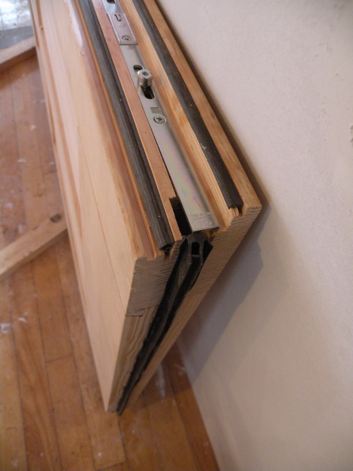
 6. The rebated, double gasketed Linnwood doors were tight except at the bottom corners were the adjustable sill sweep met the side gaskets. They did not overlap or join together and air was allowed to leak.
7. There was also some expected leaking at the taped joints of the plastic air barrier in the basement. The 3M red tape was inferior to the Siga tapes. I tried the economical approach with just using the red tape, but will have to reseal spots with better tape. I will be trying a more local importer of quality tapes - Pro-Clima tapes from FourSevenFive in NJ.

In the last post I described how I was able to see the melted spots on the roof and identify escaped heat. How exactly the heat was escaping and why was somewhat unknown.
I assumed air was allowing the heat to get through the envelope above the top of a wall on the second floor. We found that the wall plate penetrated the envelope creating a thermal break and the air sealing was not great. This was confirmed with a blower door test. We were able to see and feel warm air coming from underneath the ceiling sheetrock. It was warm air we were able to see because it was not very warm in the house and it was a sunny day, so the heat from the metal roof was coming in through the cracks. This was later in the day and all the morning frost was melted from the roof.
I also felt into the cavity around the cellulose where the melted spots were seen. So the insulation contractor offered to come back to densify the area I was concerned with. I retaped the seems around where the new cellulose was injected, caulked the ceiling sheetrock/plastic air seal and called it good. apparently the sheetrock did not make a good seal with the gasket that seal it to the plastic air barrier that was taped to the top plate of the existing wall.
The tape was not ideally used here either as the top plate was rough cut wood which it not really appropriate for taping to. Unfortunately, caulk is the best method for sealing to this.
On the next frosty morning we had a light snow. It was accumulating everywhere lightly and the house was warm. The spots of concern were not melting! This was a good sign. It was also noticed that the last areas that were not air sealed around the entry doors, because they were just installed, were melting, showing the warm air's path of least resistance.
Part 2 - The first blower door test.
This test was conducted before all air sealing was done and the plumbing lines were all open so we were not able to get any numbers. But we did find our leaks after most visual air sealing was complete. What we found:
1. a gasket on the upstair door to the cold attic has a gasket on backwards and was letting air in under the door.

3. The vaporblock seal taped connection of the 10 mill plastic air seal connector to the handhewn wood sill that sits on the granite foundation. Poor tape for the job. Probably needed to be adheared with some kind of caulk.
4. The site built bulkhead door was not gasketed. Easy fix, add gasket.
5. The second floor joists penetrated the sheetrock air barrier and were taped with Siga tape. Taping to rough sawn wood is not working.
7. There was also some expected leaking at the taped joints of the plastic air barrier in the basement. The 3M red tape was inferior to the Siga tapes. I tried the economical approach with just using the red tape, but will have to reseal spots with better tape. I will be trying a more local importer of quality tapes - Pro-Clima tapes from FourSevenFive in NJ.

Subscribe to:
Posts (Atom)